|
Pequest Trout Hatchery Updates Its Flow Control Monitoring System
by
Jeff Matthews, Hatchery Superintendent
Clint Decker, Crew Supervisor - Building Maintenance Programs
February, 2007
Moving Water
|
At
the Pequest Trout
Hatchery, flowing water is life! Clean, moving, cold water
is essential to the success of a trout rearing facility. Six
artesian wells provide the hatchery with up to seven thousand
gallons of water per minute. Remaining at 52 degrees Fahrenheit
year round, and capable of maintaining a continuous flow, the
water supply is a critical factor in propagation and maintaining
a trout production cycle.
The
hatchery sits in the Pequest River Valley over the Basin Aquifer/Valley and Ridge Sedimentary Units, a water-logged limestone formation. The topography
serves as a huge natural funnel, channelling precipitation trapped
between granite mountains on both sides to the valley floor,
replenishing the aquifer.
|
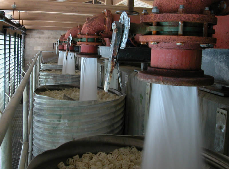
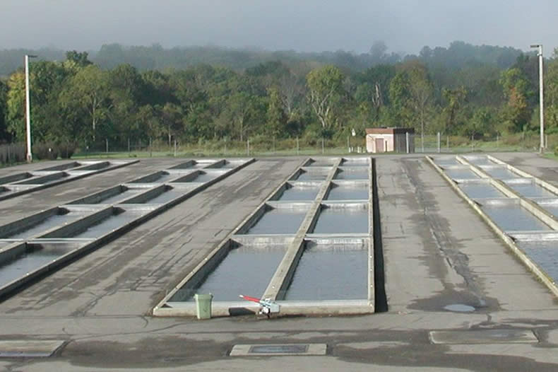
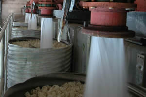 Water
flows through the hatchery in the upper aerator building.
Water
flows through the hatchery in the upper aerator building.
Click
to enlarge |
The
Hatchery Water Flow
The
hatchery's water flow begins with the six wells sunk deep into the
aquifer. Powerful vertical turbine pumps, some as large as fifty horsepower,
bring water to the surface. It then travels through large pipes to
flow meters in the well houses.
|
|
Measured
in gallons per minute (GPM), the water is sent through an underground
manifold, eventually arriving at the Upper Aerator Building.
Here the water spills out and goes through tanks filled with
"biorings" for aeration.
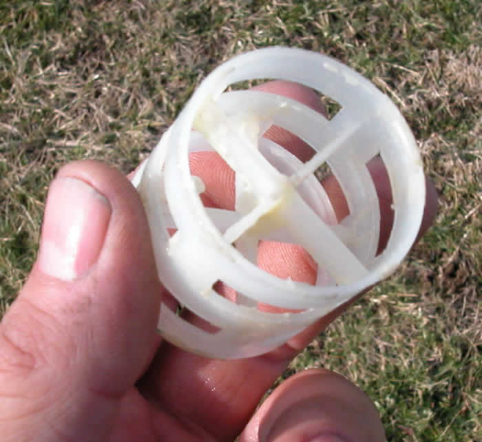
Biorings
are small cylindrical plastic structures that allow oxygen to
be induced into the low-oxygen ground water. After passing through
and being aerated by the biorings, the water is piped underground
to a distribution box and sent to the four double upper raceways.
|
|
|
After
traveling the length of those raceways, the water flows to the
lower aerator building where the aeration process is repeated.
The water flows through the four double lower raceways, to the
broodstock raceway, and then through a sluiceway into the Pequest
River.
From
September to the end of May a portion of the water is sent to
the Nursery Building. Here eggs are incubated and newly hatched
fry and fingerlings are raised. Most of the water in the nursery
is recycled, flowing from the upper aerator to a wall tank that
runs along each side of the building and then into individual
fry tanks. From the tanks the water is collected and pumped back
to the aeration building and out to the raceways.
|
|
The water at Pequest must flow continually, twenty-four hours a day,
year round, without any interruptions. So what makes this happen reliably
and efficiently? Large motorized pumps and...a new flow monitoring control
system!
Out
With the Old!!!
|
|
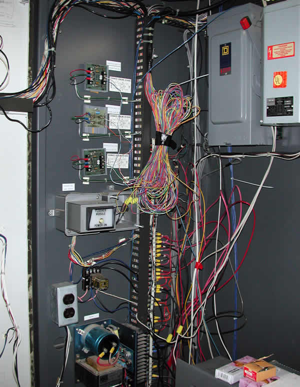
The
hatchery's old flow control and monitoring system was divided
into two systems. Three well houses were hardwired directly
to the Nursery Building, and the other three used touch-tone
telemetry technology over telephone lines. These all connected
to an alarm panel in the nursery and were integrated into a
system that would monitor all parameters of the system. The
three wells that were hardwired (2, 3, and 4) are close enough
to the nursery building to be run in conduit underground, but
wells 1, 5, and 6 are much farther away - more than a mile in
the case of Well 5.
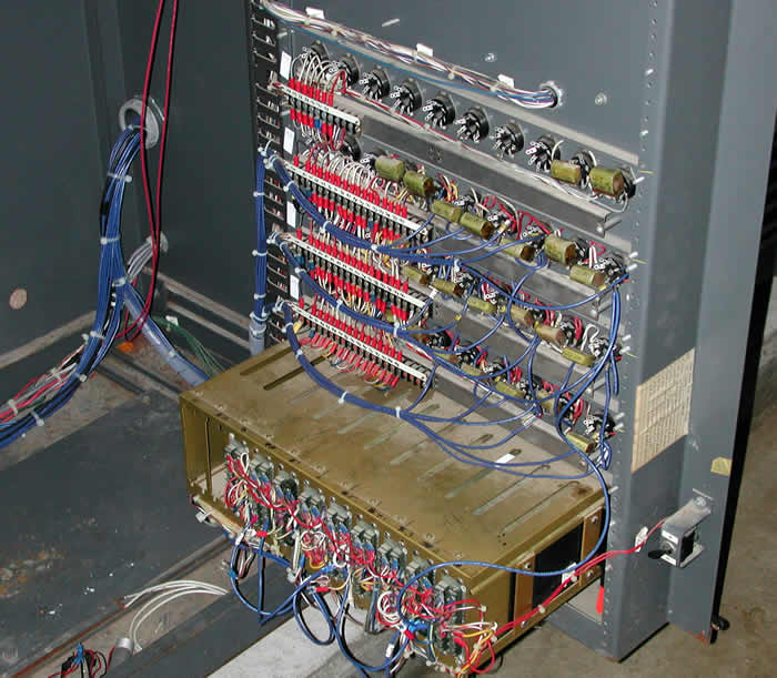
At the time of the hatchery's construction tone telemetry was
state of the art. It takes a command, converts it into tones
and transmits them over a phone line. A receiver hears that
tone, recognizes it, and performs the task that was asked of
it. This worked well for many years. However, like anything
in the technology field it became outdated and obsolete over
time. The company that made the equipment went out of business,
making repairs or obtaining replacement parts almost impossible.
There also was an ongoing concern that if a tree fell on the
telephone lines it could take out multiple wells, endangering
the hatchery's fish.
Although
Wells 2, 3, and 4 are hardwired, they are still a distance from
the control center (Well 2 is the closest of the group and still
over 1000 feet away). This created problems, particularly due
to the underground wiring being outdated and vulnerable to moisture.
The
issue became determining the kind of system which would do the
best job. Considerable time was spent investigating alternatives
and options. It also included researching the best way to solve
problem issues and provide a system that would stand the test
of time.
|
The
Solution
The solution is a wireless system using spread spectrum radio technology.
This is the same technology the military uses on the battlefield to
transmit critical data. There are tremendous benefits, first being
the elimination of maintenance on telephone lines or concern over
water in the underground wiring system. After some research, Campbell
Scientific was contacted because of their specialization in aquaculture
facilities all over the world. After a consultation with their representative,
project specifications were developed and bids requested. The contract
was awarded to BLU
DOT INC. and work began in the fall of 2005.
|
The
first step was a complete evaluation of the old system. A review
of original plans and tracing existing wires was completed.
Decisions were made on what was still useful and what had to
be removed. After the old wiring was removed and obsolete components
removed from the control panels, the new equipment was installed
along side the existing components. The old system remained
partially functional while the installation of the new equipment
was being completed.
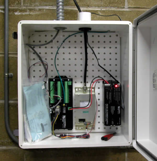
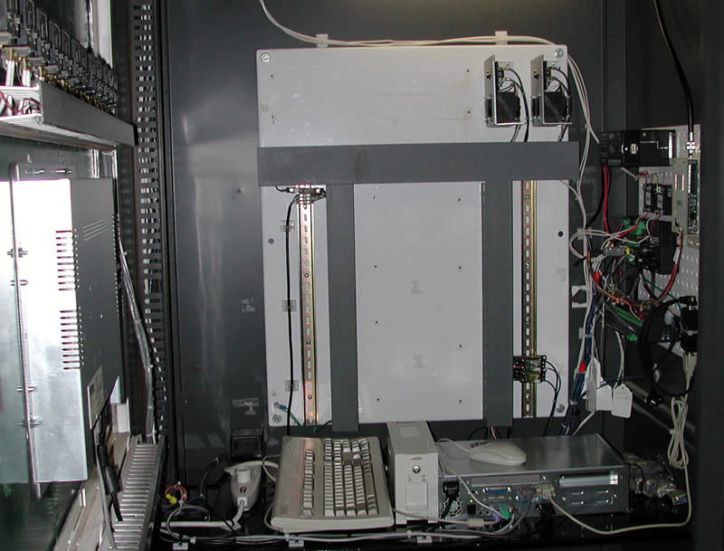
The
new system starts with a "spread
spectrum" radio and antenna connected to a data logger
at each location. The loggers in turn hook up to corresponding
devices. These control each well pump, monitor alarm parameters
and show pump run status. Also hooked up to the data loggers
are the flow meters in each well house.
|
|
The
state of backup diesels in well houses 1, 2, and 5 is also monitored.
These diesels power the pump in the event of a power failure. Wells
3 and 4 can be operated during a power failure with a backup generator,
also monitored by the new system. All data is transmitted back to
the Nursery Building where it can be monitored during regular and
emergency situations.
|
|
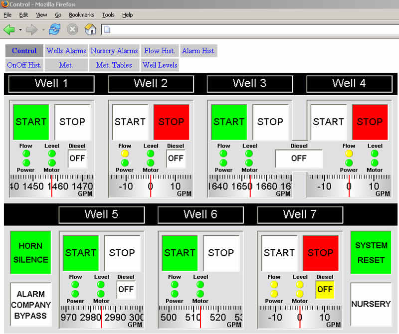
The
user interface with the new system is a 15" touch screen
mounted in the Nursery Building. From this panel the entire
operation of control and command of the wells takes place. The
panel has five different screens: Control, Well Alarms, Nursery,
Alarm History, and Weather. Each screen has a purpose:
- The
Control
Screen manages the operation of the electric pump
motors.
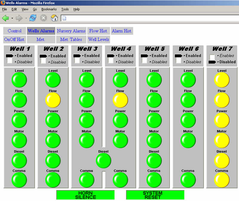
- The
Well
Alarm Screen controls all the enabling and disabling
of each alarm parameter.
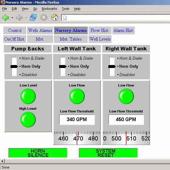
- The
Nursery
Screen displays and controls the status of all nursery
water systems (wall tanks, pump backs and incubator flows).
It will also contains the Totalizer, measuring GPM for each
well and total hatchery flow.
- The
Alarm
History Screen records every event with a time stamp,
making troubleshooting any problem much easier than in the
past.
- The
Weather
Screen displays the current outside conditions.
|
All
monitoring is done in the nursery and at two remote computers within
the hatchery complex. The system is continuously monitored. Any alarm
condition sets off an external siren on the raceways and notifies the
alarm monitoring company. Staff is notified and immediately reports
to the monitoring stations to evaluate the emergency.
|
This
system is PC-based (an industrial computer using Windows XP),
unlike our old system, and has been integrated into our local
computer network. This is another benefit of this system, allowing
us to connect the monitor computer to our network and have the
system running on computers in two different buildings. This
redundancy within the system allows for control and monitoring
in an emergency condition should one of the links in the system
fail to work.
The
radios in the well houses and the one in the nursery (which
is the base station) constantly communicate, sending packets
of data every few seconds and continually updating information.
The system also has an alarm should the base station lose contact
with one of the satellites for any length of time.
|
|
|
|
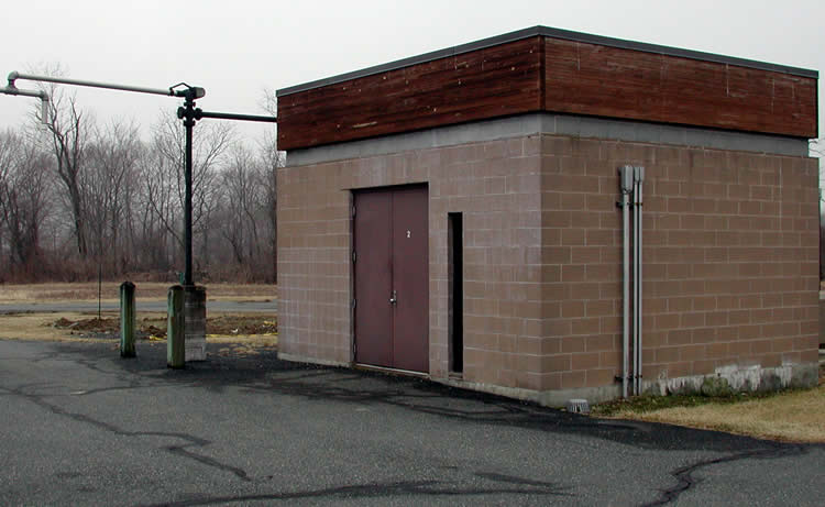
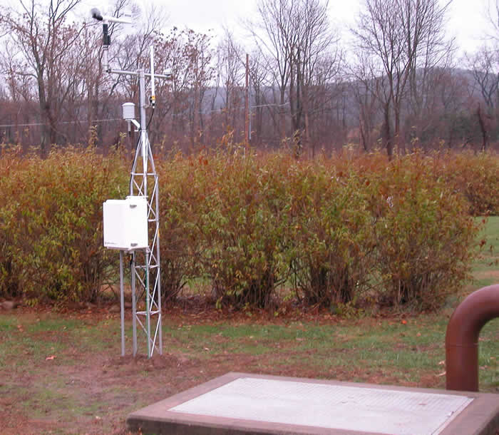
Another
benefit of the new system is the solution to a problem in Well
3. Well 3 is in an underground vault in front of the main building.
With no place to easily mount an antenna, it was suggested by
BLU DOT INC. that a ten-foot meteorological tower, with the
transmitting antenna, be installed.
The
weather station automatically tracks precipitation and cross-references
it to our well's water levels. The station sends the weather-related
data to the nursery for use by the staff, and a weather database
has been developed to monitor conditions in the Pequest Valley.
(See Weather
Screen display.)
|
|
Pressure
transducer probes have been installed in the wells to monitor
and record well water levels. This is invaluable to protect
the huge investment in the vertical turbine pumps and motors.
Severe damage could occur if water levels are too low in the
wells.
The
system sends warning alarms when water levels are getting too
low, and adjustments are made to raise the water level in the
affected well. If the condition gets too severe, the motor will
shut down.
|
|
Other
benefits are that the radios have a very low current draw, meaning they
can stand alone for almost thirty hours without line voltage, running
off a 12-volt rechargeable battery. Valuable information will not be
lost and monitoring will continue during any power outage.
|
|
Overall,
the new system to date has been working without a problem. It
also is expandable and can be upgraded on an as-needed basis.
When well 7 is completed and comes online it will be very easy
to add it to the system.
Dealing
with a live product - in this case trout - there is no room
for mechanical malfunctions. The new flow control and monitoring
system has brought the hatchery back to being one of the most
modern and efficient trout hatcheries in the nation.
|
|
